Table of Contents
This is an old revision of the document!
6. Optics for astronomy
1. Geometrical optics
Index of refraction
$$ n(\lambda) = \frac{c}{v(\lambda)} $$
where $c$ is the phase velocity of light in vacuum and $v$ is the velocity in a medium with index of refraction $n$ at a particular wavelength $\lambda$.
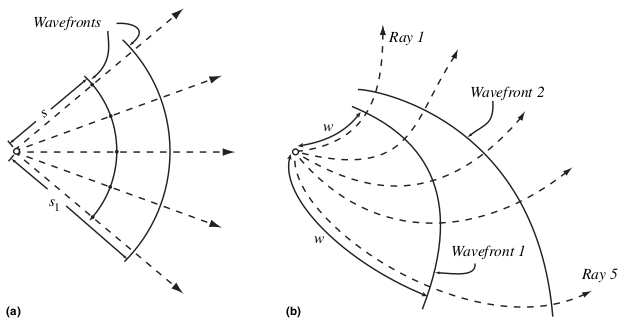
Wavefronts are perpendicular to rays. The distance traveled by a ray or front
$$s = \frac{ct}{n}$$
and the each ray will have a different $s$ is $n$ of the material is not homogeneous. In the inhomogeneous case, light rays are not straight and wavefronts are not spherical.
The light travel time along a ray
$$ t = \int \frac{ds}{v} = \frac{1}{c} \int n\,ds = \frac{w}{c} $$
where $w=\int n\,ds$ is the optical path length.
A coherent source emits all light in phase, and in this case the geometrical wavefronts also correspond to surfaces of constant phase called phase fronts.
1.1 Reflection and refraction
The French mathematician Fermat proposed a striking mathematical principle that can explain the behavior of light during reflection and refraction. The principle can be expressed in terms of the minimum optical path length $w$ as
$$ \frac{dw}{dy} = \frac{d}{dy} (s_1n_1+s_2n_2) = 0 $$
that is, light always tries to minimize the optical path length $w$ with respect to the distance $y$ along the interface between two mediums.
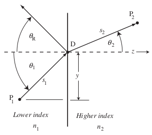
From this, we can derive Snell’s law of refraction
$$ n_1 \sin\theta_1 = n_2\sin\theta_2 $$
and if $n_1=n_2$ we get the law of reflection
$$ \theta_1 = -\theta_R $$
where the negative sign comes because of the sign convention.
Total internal reflection happens when light enters from high-index medium to low-index medium at an angle greater than the critical angle
$$ \theta_C = \sin^{-1} \frac{n_1}{n_2}. $$
If the angle of incidence is equal to the critical angle, the angle of refraction is 90 degrees.
Fresnel’s formulas give the relative intensities of the reflected and refracted rays, but they require knowledge of more advanced electrodynamics which we are not considering here. But it is important to know the reflectance of a surface and the effects of polarization of light.
Polarized waves have their electric and magnetic field vectors oscillating in only one direction. If the electric field vectors oscillate perpendicular to the plane of incidence, the case is called ‘transverse electric’ or TE and if the magnetic field vectors are perpendicular to the plane, the case is named ‘transverse magnetic’ TM. For both of these waves and for both external and internal reflection, we can define reflectance, for the angle of incidence $\theta_1=0$, as
$$ R = \left(\frac{n_1-n_2}{n_1+n_2}\right)^2 $$
and analyze its maxima and minima. This $R$ increases with the angle of incidence and $R\rightarrow 1.0$ when $\theta_1\rightarrow 90^\circ$. When light rays fall on a surface at a very large angle of incidence, the phenomenon is called grazing incidence and almost light is reflected in this case. For internal reflection, $R=1.0$ when angle of incidence is greater than the critical angle.
If $\theta_1$ is not 0 or 90 degrees, then $R$ is always smaller for TM than for TE polarization. So unpolarized light gets polarized after reflection from a dielectric surface because of the preferential reflectance. At the Brewster’s angle
$$ \theta_P = \tan^{-1} \frac{n_1}{n_2} $$
reflectance $R=0$ for TM polarization and only the TE polarization is reflected.
1.2 Spherical interfaces

The concave spherical surface has vertex $V$, center of curvature $C$, radius of curvature $R$ and the optical axis is defined by CV. An object located at $O$ creates an image at $I$ as showed by the rays incident at an angle $\theta$ at point $P$ on the surface.

In the paraxial approximation (figure above) it is assumed that the rays are parallel to the optical axis and the angles of reflection are very small, which is valid in astronomy! THINK WHY! In this approximation,
$$ \frac{2}{R} = \frac{1}{f} = \frac{1}{s_o} + \frac{1}{s_i} = -P $$
where $f$ is the focal length FV of the mirror, $s_o$ and $s_i$ are the object distance and image distance, and $P$ is the power of the surface expressed in the units of m$^{-1}$ or diopters. The light gathering power is the inverse of the focal length and it depends on the surface are of the mirror, i. e. on the square of the diameter.

For refraction at a spherical interface
$$ \frac{n_2}{s_2} - \frac{n_1}{s_1} = \frac{n_2}{f_2} = -\frac{n_1}{f_1} = P_{12} $$
where $P_{12}$ is the power in diopters. Positive $P$ tells you how strongly converging a lens is, and vice versa.
2. Mirrors and lenses
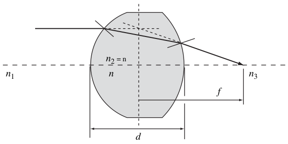
For a thick lens
$$ P = \frac{1}{f} = P_{12} + P_{23} - \frac{d}{n} P_{12}P_{23} $$
but for a thin lens where $d\rightarrow 0$
$$ P = \frac{1}{f} = P_{12} + P_{23} = \frac{1}{s_2}-\frac{1}{s_1} = (n-1)\left(\frac{1}{R_{12}}-\frac{1}{R_{23}}\right) $$
meaning a thin lens is mathematically equivalent to a mirror.

You have done ray-tracing like this at school. Similar ray tracing techniques are utilized in gigantic computer programs to find the behavior of modern telescopes.
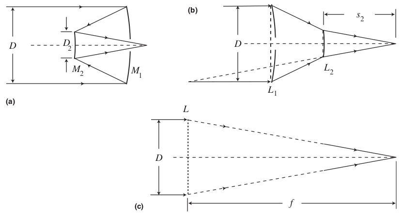
In most telescopic systems, multiple optical elements are used together. The combined power of two thin lenses separated by distance $d$ is
$$ P = \frac{1}{f} = P_1+P_2-dP_1P_2 $$
if refractive index of the surrounding $n=1$ and $P_1$ and $P_2$ are the powers of the two lenses.

A thick plane-parallel plate does not diverge or converge rays, but shifts the position of focus of already diverging and converging rays by an amount
$$ D = d\left(1-\frac{1}{n_2}\right) $$
where $d$ is the thickness of the plate. These plates are used in astronomy as filters, windows and other elements.

Optical fibres are used in astronomy for transferring light from the focal plane to somewhere else for further analysis. Sometimes putting a large spectrometer or detector or sensor at the focal plane is not practical as it obstructs the optical path, so optical fiber openings are placed at the focal plane instead.
Prisms
3. Simple telescopes
The image scale $s$ is the angular distance on the sky that corresponds to a unit linear distance in the focal plane of the camera.
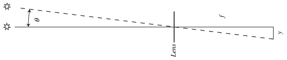
$$ s = \frac{\theta}{y} = \frac{1}{f} $$
if $\theta$ is in radians, but
$$ s = \frac{206,265}{f} $$
arcsec / m. Modern telescope detectors have many light-sensitive pixels on the focal plane. If the pixels are separated from each other by a distance $d$, then the pixel scale $s_p=sd$ which is the angular size on the sky imaged by one pixel.
The size and shape of a detector determines the field of view of a camera. A detector of length $l$ and width $w$ will have a field of view of $sl\times sw$.
Focal ratio
$$\mathcal{R} = \frac{f}{D}$$
where $D$ is the diameter of the aperture. If a 114 mm mirror has a focal length of 450 mm, its $\mathcal{R}=3.95$ and it is often expressed as f/4 (focal length is four times larger than the aperture).
The brightness of an extended source at the focal plane is proportional to $\mathcal{R}^{-2}$. So images in a f/4 system will be four times brighter than images in an f/8 system.

Amateur telescopes have oculars or eyepieces and and in that case the object is magnified by a factor
$$ M = \frac{\theta'}{\theta}. $$
The diagram shows
$$ M \approx \frac{\tan\theta'}{\tan\theta} = \frac{y/f'}{y/f} = \frac{f}{f'} $$
meaning the ratio of the focal lengths determine the magnification.
4. Resolution and quality

George Airy said that light from a point is seen as a diffraction pattern through an aperture and the 84% of the light is concentrated in the central patch, the Airy disk. The angular radius of the Airy disk
$$ \alpha_A = 1.22 \frac{\lambda}{D} \text{[radians]} = 0.252 \frac{\lambda}{D} \text{[arcsec m $\mu$m$^{-1}$]} $$
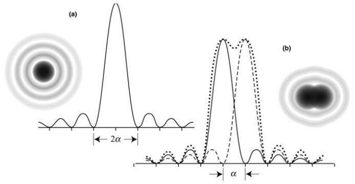
The Rayleigh criterion states that two sources are considered resolved if the distance between the centers of their Airy disks is not less than $\alpha_A$.
The resolution of a space telescope is determined solely by its diffraction limit, the value of $\alpha_A$. But for ground-based telescopes, atmospheric seeing introduces the most dominant factor.

Near the Earth’s surface a temperature change of 1 $^\circ$C creates an index change of $10^{-6}$. Different lumps of air have different indices.
You can freeze the speckle pattern in very short exposures of less than 1/20 s. In a single short exposure the number of speckles is almost $(D/r_0)^2$ where $r_0$ is the typical diameter of an atmospheric lump. Speckle interferometry utilizes these short exposures to remove the speckle pattern and recover the diffraction-limited image, but it is only possible with large apertures and bright sources.
Normally all speckles are blurred to produce a single seeing disk of radius
$$ \alpha_s \approx \frac{\lambda}{r_0}. $$
Telescopes with aperture smaller than $r_0$ do not produce the speckle pattern but a single Airy pattern; in this case the brightness of the source fluctuates; the effect is called scintillation. Our eyes have 7-mm aperture and see the twinkling of stars.
4.1 Atmospheric refraction
Earth’s atmosphere can be approximated as a series of plane-parallel plates.
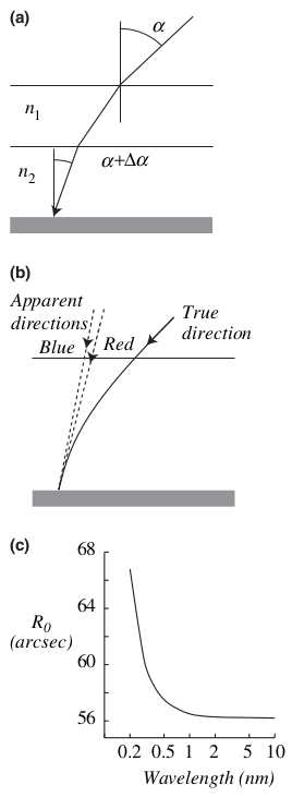
In (a), two such ‘plates’ are shown where $n_2>n_1$ and the position of an object is shifted by $\Delta\alpha$ toward the zenith because of refraction. In (b) many layers are assumed and their combined result gives a shift
$$ -\Delta\alpha \approx (n-1)\tan\alpha $$
where $n$ is the index of refraction of the light-gathering surface (dark gray). The quantity $(n-1)\times 10^6$ is named the refractivity. The refractivity is plotted in panel [c] above in arcsec, not in radians multiplied by 1 million.
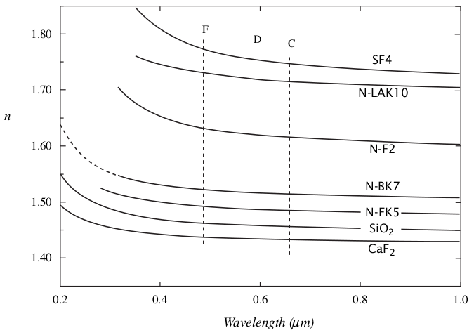
4.2 Chromatic aberration

As shown in Section 2.1, the index $n$ decreases with wavelength for optical glasses. As $\lambda$ increases, $n$ decreases and, hence, the focal length $f$ increases. So red light is focused farther away from the vertex compared to blue light. This is chromatic aberration because it depends on color.
It occurs only in refracting systems, so only if the telescope is made of lenses.
It can be corrected by connecting a high-dispersion low-power lens with a low-dispersion high-power lens as shown above. Such elements are called achromat. An achromat can bring two wavelengths to a common focus. There are apochromats that can bring three different wavelengths to a common focus and superapochromats that bring four different wavelengths to a common focus.
5. Aberrations
5.1 Monochromatic wavefront aberrations
For reflecting systems, chromatic aberration does not occur. But even monochromatic light (light of just one wavelength) can have differing focus after getting reflected from a mirror.

The plane of the diagram (a) is called the tangential plane and the plane perpendicular to it is called the sagittal plane. The chief ray $V'VF$ and the ray $CFBFC$ are shown on the tangential plane. The test ray $P'PF$ could be on a different plane than the tangential and sagittal.
Diagram (b) shows the plane of the aperture and a point here can be described by the spherical polar coorcinates $\phi$ and $\rho$ (radius) and the distance $b=R\sin\theta$ that gives the distance of the source from the optical axis, $R$ being the radius of curvature.
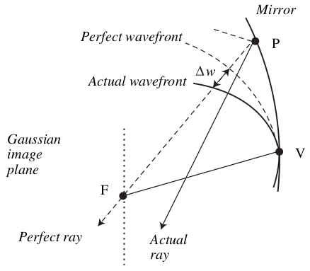
The focal plane for the perfect focus is called the Gaussian image plane, and the distance from this image plane of the point where the actual ray meets the optical axis can be measured using the quantity $\Delta w$ which is located by the coordinates $\rho,\phi$ and the distance $b$.
In third-order aberration theory (where $\sin\theta \approx \theta - \theta^3/3!$), it has been proved that
$$ \Delta w(\rho,\phi,b) = C_1 \rho^4 + C_2 \rho^3 b \cos\phi + C_3 \rho^2 b^2 \cos^2\phi + C_4 \rho^2 b^2 + C_5 \rho b^3 \cos\phi $$
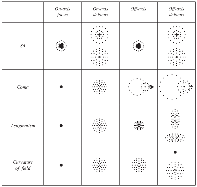
where the coefficients $C_i$ depend on the detailed shape of the reflecting surface. The five terms in this equation are responsible for five different types of aberrations called the Seidel aberrations as given below.
| Aberration | Functional dependence |
|---|---|
| Spherical aberration | $\rho^4$ |
| Coma | $\rho^3 b \cos\phi$ |
| Astigmatism | $\rho^2 b^2 \cos^2\phi$ |
| Curvature of field | $\rho^2 b^2$ |
| Distortion | $\rho b^3 \cos\phi$ |
The list is given in order of importance. Because spherical aberration (SA) is the most prominent, it is corrected for first, and then the effect of ‘coma’ is corrected, and so on.
5.2 Surface shapes
Spherical mirrors are the easiest to make, but other shapes are created by rotating a conic section around its axis of symmetry.

Panel (a) shows the $y-z$ coordinates of the system, where $z$-axis is along the optical axis and also the axis of symmetry of a conic section. The cross-section of a mirror surface satisfies the equation
$$ y^2 = 2Rz - (1-e^2)z^2 $$
where $e$ is the eccentricity of the conic and $R$ the radius of curvature at the vertex.
| Shape | Eccentricity |
|---|---|
| Sphere | $0$ |
| Oblate ellipsoid | $0<e<1$ |
| Prolate ellipsoid | $e^2<0$ |
| Paraboloid | $e=1$ |
| Hyperboloid | $e>1$ |
5.3 Spherical aberration
All aberrations except SA vanishes on axis when $b=0$, but SA remains. If the source is exactly at the center of the field of view, SA is the only aberration to take care of.
As shown below, two rays coming from an on-axis source strike the axis at two different points $F$ and $G$ where G is at a distance $0.845(R/2)$ from the vertex.

The focal length of a conic of revolution
$$ f(\rho) = \frac{R}{2} - (1+K) \left[\frac{\rho^2}{4R}+\frac{(3+K)\rho^4}{16R^3}+...\right] $$
where the first term gives $R/2$ gives the Gaussian focus, $\rho^2$ is a third-order aberration term and $\rho^4$ is a fifth-order aberration term. The conic constant $K=-e^2$.
The actual image is blurred and formed not in the Gaussian plane but in the plane of least confusion.
Large focal ratio minimizes both chromatic and spherical aberration of lenses. The the blur due to SA can be reduced down to the size of the seeing disk almost.
For mirrors, a paraboloid has zero SA, because $K=-1$.
A Schmidt telescope modifies a spherical reflector to have minimal SA.
5.4 Coma
Before the invention of photography, astronomers did not care about off-axis sources.
Among the four off-axis aberrations, coma and astigmatism degrade image resolution, and the curvature of field and distortion only change the position of the course.
Both coma and SA are problematic mainly for large apertures because of the large exponent of $\rho$.
Coma depends on $\rho^3 b \cos\phi$, so it increases with distance of the object from axis.

In this sagittal plane diagram, rays are coming off-axis at an angle $\theta$, here we are talking about a constant distance from the vertex $\rho$. The rays form a ring-shaped offset from the Gaussian focus. The farther the ray (its meeting point on the Gaussian plane) is from the Gaussian focus, the bigger the ring. So the overall offset creates a shape like a comet, hence the name coma.
The angular size of the blur due to coma
$$ L = A\frac{bD^2}{f^3} = A\theta \mathcal{R}^{-2} $$
where $D$ is the diameter of the aperture, $\mathcal{R}$ is the focal ratio, and $A$ depends on the shape of the surface.
An optical system with neither SA nor coma is called aplanatic which can only be achieved by using multiple optical elements together.
5.5 Astigmatism
Astigmatism depends on $b^2\rho^2 \cos\phi$ and, hence, it increases more rapidly than coma for off-axis points in an image.
In the sagittal plane, $\phi=90^\circ$ or $270^\circ$ and, hence, coma is zero. It is maximum in the tangential plane ($\phi=0^\circ$ or $180^\circ$).

The tangential rays focus on the Gaussian focus on the sagittal plane, and this focus is the tangential focus. The sagittal rays focus on a sagittal focal point $S$ farther away. The compromise focus is somewhere in between.
The image of a star at the compromise focus has a length due to astigmatism
$$ L_{astig} = B\theta^2 \mathcal{R}^{-1} $$
where $B$ depends on the detailed structure of the aperture surface.
A Schmidt-Cassegrain system is anastigmatic aplanat.
5.6 Field curvature

Off-axis images fall on the Petzval surface.