Table of Contents
V. Current and resistance
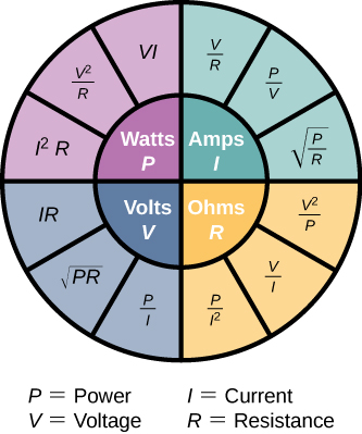
By the end of this lecture, you will understand all the relations shown in the following figure.
1. Electrical current
Electrical current is the rate of flow of charge through an area A per unit time.

In other words
$$ I = \frac{dq}{dt} $$
and its unit must be C/s (coulomb per second) which is named ampere (A).
If the charge through a cross-section is described as a function of time as $Q(t)=Q_M(1-e^{-t/\tau})$ where $\tau$ is a time constant, than the current will be just a time-derivative of this or $I(t)=Q_M(e^{-t/\tau})/\tau$. These two are plotted above.
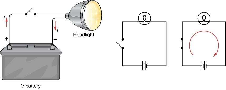
When the switch is closed, current flows in the direction given on the right-most panel. The signs for the battery, switch and bulb are indicated. Even though electron actually moves from negative (short bar) to positive (long bar) terminals of the battery, conventionally the direction of the current is always taken to be from positive to negative.

Electrons flow opposite to the electric field, but the conventional current is taken to be toward the electric field.
2. Conduction in metals
Electrical signals are carried at a speed very close to the speed of light, $10^8$ m/s.
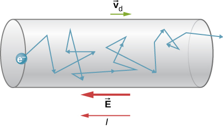
But the individual electrons that carry the signal actually travel at a much lower speed called the drift velocity ($\vec{v}_d$), only around $10^{-4}$ m/s. The electrons continually collide with other electrons and particles and, hence, moves a very small distance in 1 second. However, as all the electrons push each other in a single direction (opposite to $\vec{E}$), the electron at the very end of a wire is affected almost instantaneously as the very first electron.
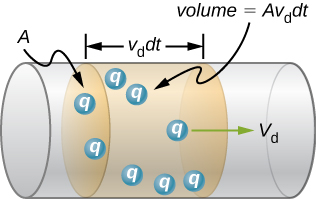
The total charge within the shaded section $dq=nqAv_d dt$ where $q$ is the charge of a single carrier and $n$ is the number of charges per unit volume. So the current
$$ I = \frac{dq}{dt} = qnAv_d \Rightarrow v_d = \frac{I}{nqA} $$
which gives the relation between drift velocity and current. They are directly proportional to each other.
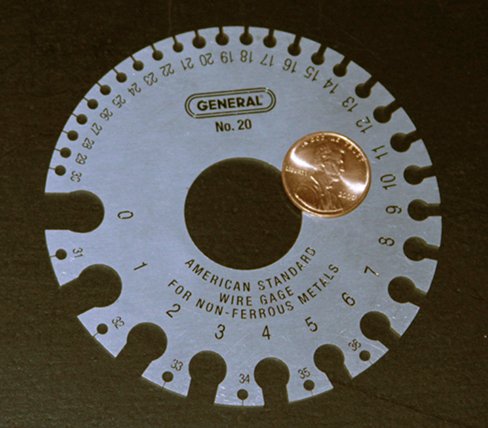
Current depends on the cros-sectional area of a cylindrical wire and, hence, on its diameter. The diameter of wires is standardized using the units of gauge. Larger gauge means smaller diameter. A device for measuring gauge is shown above.
2.1 Current density
Current, a scalar quantity, gives the overall rate of flow of charge. If you want to know the details of the motion of charges, use the vector quantity current density, $\vec{J}$.
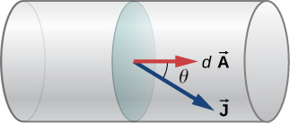
Current density is the current per unit area, unit must be A m$^{-2}$. Mathematically, current
$$ I = \iint \vec{J} \cdot d\vec{A} = \iint J dA \cos\theta $$
where $\theta$ is the angle between the current density and area vectors. as shown in the figure. Considering only the magnitude,
$$ J = \frac{I}{A} = \frac{n|q|Av_d}{A} = n|q|v_d $$
and, hence, the vector $\vec{J}=nq\vec{v}_d$. So the direction of the current density is toward the direction of the drift velocity and, consequently, opposite to the direction of the electric field.
3. Resistivity and resistance
When a voltage is applied in a material, a field is created and the charges feel a force due to the field. The resulting current density, for some materials, is directly proportional to the field:
$$ \vec{J} \propto \vec{E} \Rightarrow \vec{J} = \sigma \vec{E} $$
where $\sigma$ is the electrical conductivity of the specific material; its unit is [J}/[E] = (A/m$^2$) / (V/m) = A / (V m). If we define the unit ohm ($\Omega$) as
$$ 1 \ \Omega = 1 \ V/A $$
then the unit of conductivity is simply ($\Omega$ m)$^{-1}$. Resistivity is the opposite of conductivity, so resistivity
$$ \rho = \frac{1}{\sigma} = \frac{E}{J} $$
and its unit is simply $\Omega$ m. The temperature of a material increases due to current and the consequent increase in length can be calculated if you know the conductivity, resistivity and the linear coefficient of thermal expansion of the material. See Table 9.1 in the book.
The resistivity depends on temperature as
$$ \rho \approx \rho_0 [1+\alpha(T-T_0)] $$
where $\rho_0$ is the resistivity at reference temperature $T_0$ and $\alpha$ is the coefficient of thermal expansion.
3.1 Resistance
The previously defined $\Omega$ is actually the unit of resistance which is defined as
$$ R = \frac{V}{I} $$
which gives the familiar Ohm’s law $V=IR$ or $I\propto V$ (current is proportional to voltage). This is the reason why V/A (volt per ampere) is named ohm.
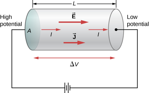
This can be related to other quantities. For the above setup
$$ E = \rho J \Rightarrow \frac{V}{L} = \rho \frac{I}{A} \Rightarrow \frac{V}{I} = R = \rho\frac{L}{A}. $$
So resistance is related to resistivity and the length and cross-sectional area of the conductor as you can see in this animation.

A resistor has two possible symbols in an electrical circuit.

The resistance of a resistor is indicated on the surface through colored stripes as shown above. Like resistivity, resistance must also depend on the temperature at which the resistor is kept:
$$ R = R_0[1+\alpha(T-T_0)]. $$
Compare with the temperature dependence of resistivity to understand the different terms.
4. Ohm's law
Already in the previous section, we encountered Ohm’s law:
$$ I \propto V \Rightarrow V = IR $$
or the electrical current is is directly proportional to the applied voltage. It is named after the German Georg Ohm because he published a paper describing an experiment similar to the one shown below.

A voltmeter connected in parallel to the resistor measures voltage, an ammeter connected in series with the resistor measures current. The results for both the positive (clockwise) and negative (counterclockwise) cases are shown below.

If a device follows the $I\propto V$ rule, it is ohmic, if not it is nonohmic. For a nonohmic device like a diode, the relationship between current and voltage is nonlinear.

A diode is shown in a circuit with a battery and a resistor in both reverse and forward biases. Current flows only in forward bias when voltage is more than 0.7 V as shown below.
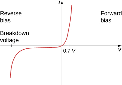
The relationship is clearly nonlinear.
5. Electrical energy and power
A positive charge moves by a distance $\Delta L$ and a potential difference of $\Delta V=V_2-V_1$ because of a force $\vec{F}=m\vec{a}=q\vec{E}$ exerted on it by the electric field $\vec{E}$.
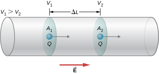
Because $V_1 > V_2$, the electric field
$$ E = -\frac{\Delta V}{\Delta L} $$
and the work done on the charge $W=F\Delta L = qE\Delta L = -q\Delta V = -\Delta U$ where $U$ is the electric potential energy.
The drift velocity is constant and, hence, kinetic energy does not change. The electric potential energy due to the work is converted to thermal energy in the material and its temperature increases. In a resistor the energy is dissipated as heat and in a light bulb as both heat and light. The power
$$ P = \frac{\Delta U}{\Delta t} = \frac{q\Delta V}{\Delta t} = I\Delta V. $$
For a general case the power dissipated by a resistor
$$ P = IV = I(IR) = I^2R = \frac{V^2}{R}. $$
The power is proportional to the square of the voltage and also to the square of the current.
The energy consumed by an electrical device
$$ E = \int P \ dt. $$
The unit of power if J/s or W (watt) and that of energy as given in electrical bills is kW$\cdot$h (kilowatt-hour) which is consistent with the relationship $E=Pt$.
$$ 1 \text{ kW h} = 3.6\times 10^6 \text{ J}. $$
In order to conserve nature or reduce electric bills, you can either reduce the time of consumption or replace the electrical appliance with something that consumes much less power. For example, CFL (compact fluorescent light) bulbs and LEDs (light emitting diode) consume much less than incandescent bulbs.
A 60-W incandescent bulb can be replaced by a 15-W CFL which has the same brightness and color. CFLs also last 10 times more than incandescents. LEDs last five time more than even CFLs. So incandescent bulbs are being phased out everywhere.
| Light Output (lumens) | LEDs (watts) | Incandescent Light Bulbs (watts) | CFL Light Bulbs (watts) |
|---|---|---|---|
| 450 | 4−5 | 40 | 9−13 |
| 800 | 6−8 | 60 | 13−15 |
| 1100 | 9−13 | 75 | 18−25 |
| 1600 | 16−20 | 100 | 23−30 |
| 2600 | 25−28 | 150 | 30−55 |
As you can see, a 6-W LED gives the same light as a 60-W incandescent bulb and a 13-W CFL bulb.
6. Superconductors
In the year 1911, the Dutch physicist Heike Kamerlingh Onnes of Leiden University was checking the temperature-dependence of resistance of mercury (Hg). He found the following.
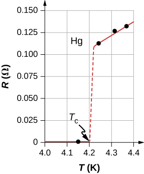
He was cooling the mercury using liquid helium and found the resistance to be linearly decreasing. But at 4.2 K, the resistance suddenly dropped to almost zero (actually 0.01 $\Omega$).
At the critical temperature $T_c=4.2$ K, mercury becomes a superconductor.

