Table of Contents
IV. Capacitance
Capacitors are used for storage of electrical energy and as filters. They are one of the fundamental elements of all circuits.
1. Capacitors and capacitance
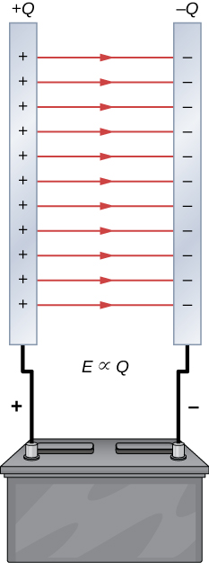
For these two parallel plates electric field magnitude $E=\sigma/\epsilon_0$ where $\sigma=Q/A$. So electric field $E\propto Q$.
The capacitance is defined as
$$ C = \frac{Q}{V} $$
and has the unit farad (F) where 1 F = 1 C V$^{-1}$. A 1-F capacitor can store 1 C of charge when the potential between its two plates is 1 V which is unrealistic. In reality, we encounter capacitors of milli (mF), micro ($\mu$F), nano (nF) or pico (pF) farads.
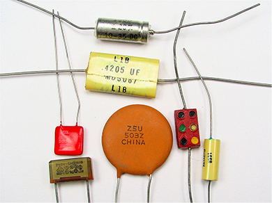
Capacitors look like this. They are usually made of two small metal foils separated by two small pieces of insulation. The whole thing is enclosed in a protective coating and two small metal leads are used for connections. Common insulating materials include mica, ceramic, paper and teflon.
An electrolytic capacitor has very high capacitance, almost 1 F. It is made using an oxidized metal in a conducting paste.
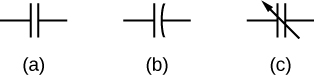
(a) normal circuit representation of a capacitor, (b) electrolytic capacitor, © variable-capacitance capacitor.
1.1 Parallel-plate capacitor
Let us calculate the capacitance of a parallel-plate capacitor. First find the electric field, than the potential ($\Delta V=\int \vec{E}\cdot d\vec{r}$) and finally the capacitance ($C=Q/V$).
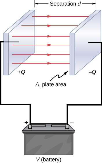
Here, electric field is already known, $E=\sigma/\epsilon_0$ where $\sigma=Q/A$. So the potential
$$ V=Ed = \frac{\sigma d}{\epsilon_0} = \frac{Q d}{\epsilon_0 A} $$
and hence finally the capacitance
$$ C = \frac{Q}{V} = \epsilon_0\frac{A}{d} $$
which miraculously does not depend on the charge but only on the area and distance of the plates or the geometry of the object. There is a dependence on the medium between the plates as well because $\epsilon_0$ is the permittivity of free space. If the material is changed to some other insulating material we have to use the permittivity $\epsilon$ of that material.
1.2 Spherical capacitor
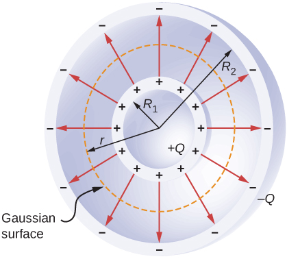
Calculate the electric field using the Gaussian surface between the shells at radii $R_1$ and $R_2$ and use Gauss’s law:
$$ \oint_S \vec{E}\cdot \hat{n} dA = 4\pi r^2 E \hat{n} = \frac{Q}{\epsilon_0} \Rightarrow \vec{E} = \frac{1}{4\pi\epsilon_0} \frac{Q}{r^2} \hat{r}. $$
Now the potential is an integration of field over a path from radius $R_1$ to $R_2$:
$$ V = -\int_{R_1}^{R_2} \vec{E} \cdot d\vec{l} = -\int_{R_1}^{R_2} \frac{1}{4\pi\epsilon_0} \frac{Q}{r^2} \hat{r} \cdot \hat{r}dr = \frac{Q}{4\pi\epsilon_0}\left(\frac{1}{R_1}-\frac{1}{R_2}\right) $$
and finally thus the capacitance
$$ C = \frac{Q}{V} = 4\pi\epsilon_0\frac{R_1R_2}{R_2-R_1}. $$
which again only depends on the geometry of the spherical capacitor.
1.3 Cylindrical capacitor
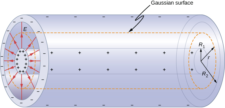
For this cylindrical capacitor, the Gaussian surface is between the two cylindrical shells.
Gauss’s law says $\oint_S\vec{E}\cdot\hat{n} dA = 2\pi r l = Q/\epsilon_0$ and hence electric field $\vec{E}=Q/(2\pi\epsilon_0 r l)\hat{r}$. So the potential
$$ V=\int_{R_1}^{R_2}\vec{E}\cdot d\vec{l} = \frac{Q}{2\pi\epsilon_0 l} \int_{R_1}^{R_2} \frac{dr}{r} = \frac{Q}{2\pi\epsilon_0 l} \ln\frac{R_2}{R_1} $$
and hence the capacitance
$$ C=\frac{Q}{V} = \frac{2\pi\epsilon_0 l}{\ln(R_2/R_1)} $$
which also depends only on the geometry. Coaxial cables have cylindrical symmetry and we can find the capacitance per unit length of such a cable
$$ \frac{C}{l} = \frac{2\pi\epsilon_0}{\ln(R_2/R_1)}. $$
In a coaxial cable, the outer conductor is usually grounded and current flows in opposite direction in the two conductors separated by some insulator.
2. Combinations of capacitors
2.1 Series
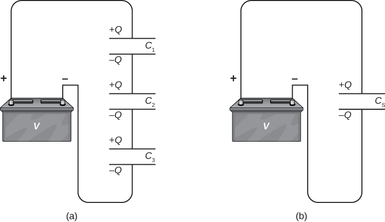
All capacitors in a series combination has the same charge. Imagine a single capacitors with capacitance $C_s$ which is equivalent to the the capacitance of all the capacitors combined.
If the voltages across the individual capacitors are $V_1$, $V_2$ and $V_3$ then the voltage across the equivalent capacitor
$$ V = V_1+V_2+V_3 \Rightarrow \frac{Q}{C_s} = \frac{Q}{C_1}+\frac{Q}{C_2}+\frac{Q}{C_3} $$
and hence the equivalent capacitance
$$ \frac{1}{C_s} = \frac{1}{C_1}+\frac{1}{C_2}+\frac{1}{C_3}. $$
2.2 Parallel
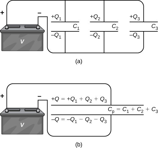
Voltage is the same across all capacitors connected in parallel. If the charges on the individual capacitors are $Q_1$, $Q_2$ and $Q_3$, then the charge on the equivalent capacitor
$$ Q_p = Q_1+Q_2+Q_3 \Rightarrow C_PV = C_1V+C_2V+C_3V $$
and hence the equivalent capacitance for parallel connection
$$ C_P = C_1+C_2+C_3. $$
3. Energy storage
Energy stored in a capacitor is electrostatic potential energy $U_C$. It is quantified using the energy density $u=U_C/(Ad)$ where $Ad$ is the volume of the space between the plates. We will later (in another chapter) derive that $u=\epsilon_0E^2/2$. So the energy stored
$$ U_C = uAd = \frac{1}{2}\epsilon_0 Ad E^2 = \frac{1}{2}\epsilon_0 Ad \frac{V^2}{d^2} = \frac{1}{2}V^2\epsilon_0\frac{A}{d} = \frac{1}{2}V^2 C $$
which can be expressed in other forms as well
$$ U_C = \frac{1}{2}V^2 C = \frac{1}{2} \frac{Q^2}{C} = \frac{1}{2}QV. $$
This is normally valid for all types of capacitors. While charging a capacitor, an amount of work $W$ is done on charge $dq$, so total work for charging with charge $Q$,
$$ W = \int_0^{W(Q)} dW = \int_0^Q\frac{q}{C}dq = \frac{1}{2}\frac{Q^2}{C} $$
which is exactly equal to the potential energy stored in the capacitor $U_C$.
4. Capacitors with dielectric
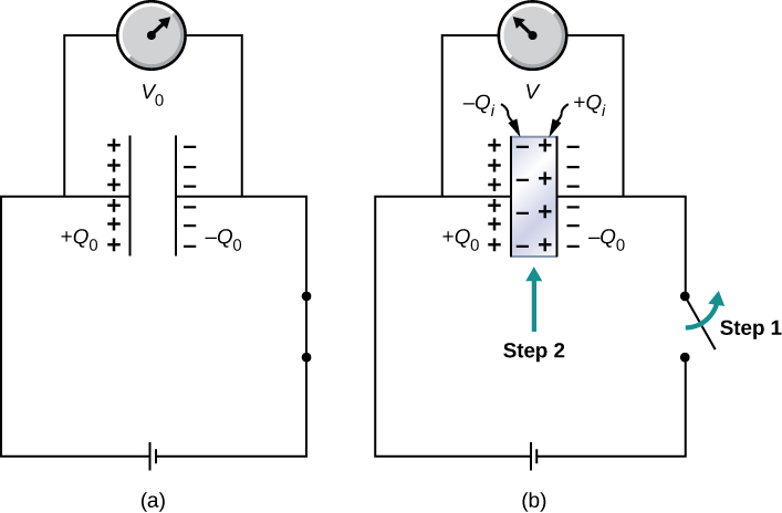
Left: a capacitor is charged by $Q$ with a battery and it has a voltage of $V_0$; there is air between the plates. Right: the battery is disconnected and a dielectric is inserted between the plates filling the whole empty volume. The voltage drops to
$$ V = \frac{1}{\kappa}V_0 $$
where $\kappa$ is called the dielectric constant characteristic of a specific dielectric medium. The voltage drops because negative charge $Q_i$ builds up in the dielectric adjacent to the positive plate and positive charges build up near the negative plate. This reduces the electric field and, hence, the potential. Now capacitance
$$ C = \frac{Q_0}{V} = \frac{Q_0}{V_0/\kappa} = \kappa\frac{Q_0}{V_0} = \kappa C_0 $$
where $C_0$ was the capacitance when there was no dielectric. The constant $\kappa>1$ and therefore $C>C_0$ always. We can say dielectric constant of vacuum $\kappa=1$. It is dimensionless because it is a ration between two similar quantities.
The energy stored is also affected:
$$ U = \frac{1}{2} \frac{Q^2}{C} = \frac{1}{2} \frac{Q_0^2}{\kappa C_0} = \frac{1}{\kappa} U_0 $$
meaning less energy is stored than when there was no dielectric.
5. Molecular model of dielectric
Molecules of a medium can be either polar or nonpolar. Nonpolar molecules do not have any dipole moment in the absence of external electric field. Polar molecules always have a nonzero dipole moment.
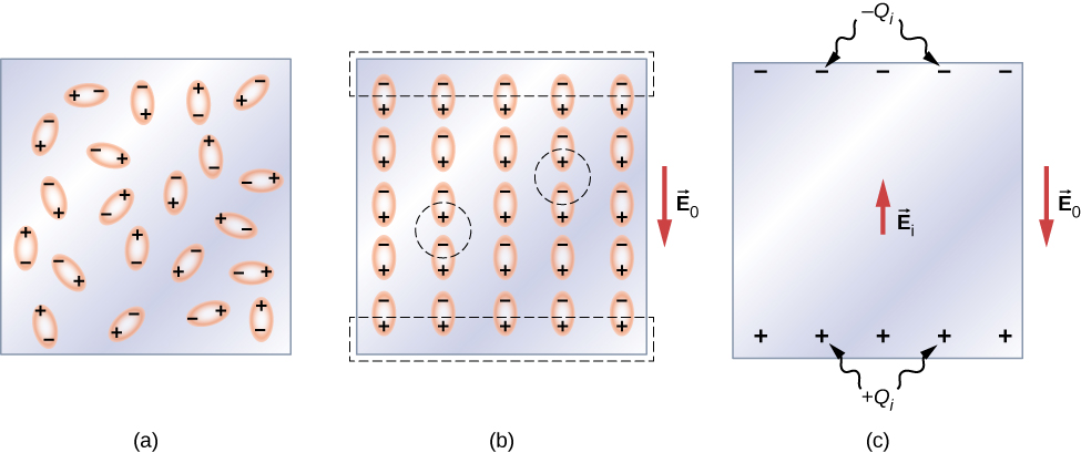
If a dielectric is made of polar molecules, the dipoles are initially oriented randomly giving no net electric field (a). When the capacitor is charged, the dipoles follow the field. Each dipole than has an induced electric field $\vec{E}_i$ opposite to the capacitor electric field $\vec{E}_0$ and hence the net field
$$ \vec{E} = \vec{E}_i + \vec{E}_0 $$
which will be less than the initial field $\vec{E}_0$ as shown below.
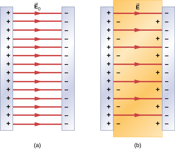
If the net field is proportional to the field $\vec{E}_0$, the dielectric constant
$$ \kappa = \frac{E_0}{E} $$
which is always greater than one. The induced electric field is then
$$ \vec{E}_i = \left(\frac{1}{\kappa}-1\right)\vec{E}_0. $$
Problems