Table of Contents
X. Inductance
1. Mutual inductance
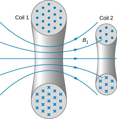
Mutual inductance of coil 2 caused by coil 1 is
$$ M_{21} = \frac{N_2 \Phi_{21}}{I_1} $$
where $\Phi_{21}$ is the flux through the coil 2 caused by the magnetic field created by the current in coil 1 $I_1$. A similar equation of mutual inductance can be written for coil 1:
$$ M_{12} = \frac{N_1 \Phi_{12}}{I_2}. $$
It can be proven that $M_{21} = M_{12}$. So dropping the subscripts we get, mutual inductance of two coils
$$ M = \frac{N_2 \Phi_{21}}{I_1} = \frac{N_1 \Phi_{12}}{I_2}. $$
The unit is henry (H) named after American scientist Joseph Henry who discovered induced emf independently of Faraday.
Prove that 1 H = 1 V s / A.
And prove that the induced emf in the two coils
$$ \varepsilon_1 = -M\frac{dI_2}{dt} \text{ and } \varepsilon_2 = -M\frac{dI_1}{dt}. $$
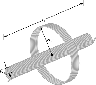
In this setup, $N_1=500$, $N_2=10$, $R_1=3.10$ cm, $l_1=75.0$ cm. In the solenoid $dI_1/dt=200$ A/s. What is emf induced in the outer coil?
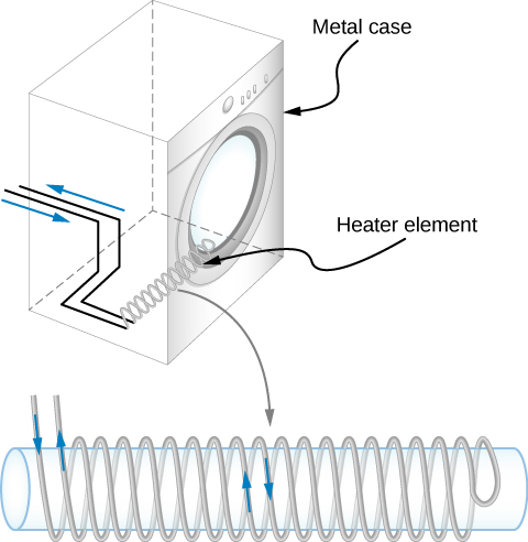
A transformer should have high $M$, but a clothes dryer shown above should not have a large mutual inductance. How can you reduce $M$ in a dryer?
2. Self-inductance and inductors
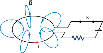
If the current varies, the self-induced emf in the circuit
$$ \varepsilon = - \frac{d\Phi_m}{dt} $$
where $\Phi_m \propto I$ or $\Phi_m=LI$. Here, $L$ is called the self-inductance of the wire loop. If the loop has $N$ turns, then $ N\Phi_m = LI$ and, hence, the induced emf
$$ \varepsilon = -L \frac{dI}{dt} $$
and so the self-inductance $L=|\varepsilon| / |dI/dt|$. This is an inductor used in a circuit.
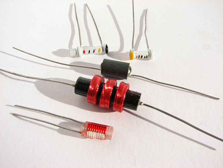
The induced emf always opposes the original current in the circuit according to Lenz’s law.

Inductors are used in street intersections in the developed world, and in metal detectors everywhere.
2.1 Solenoid
For a cylindrical solenoid the interior magnetic field $B=\mu_0 NI$ and per unit length it becomes $B=\mu_0 NI / l$.
So the magnetic flux $\Phi_m = BA = \mu_0 NAI / l$.
And the self-inductance of the solenoid $L=N\Phi_m / I = \mu_0 N^2 A / l$.
If the turns per unit length $n=N/l$, then
$$ L = \mu_0 \left(\frac{N}{l}\right)^2 Al = \mu_0 n^2 Al = \mu_0 n^2 V. $$
2.2 Toroid
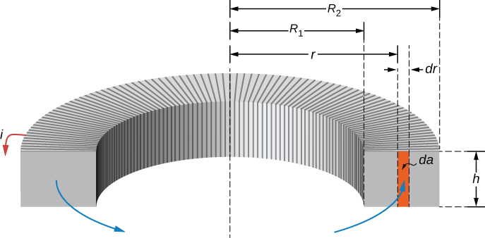
For the rectangular toroid above apply Ampere’s law to find $B=\mu_0 NI / (2\pi r)$ and so
$$ \Phi_m = \int B da = \int_{R_1}^{R_2} \frac{\mu_0 NI}{2\pi r} hdr = \frac{\mu_0 NhI}{2\pi} \ln\frac{R_2}{R_1}. $$
So the inductance of such an inductor will be
$$ L = \frac{N\Phi_m}{I} = \frac{\mu_0 N^2h}{2\pi} \ln\frac{R_2}{R_1} $$
which is only dependent on the geometry of the toroid.
3. Energy in a magnetic field
The density of electric energy stored in a capacitor was $u_E=\epsilon_0 E^2 / 2$. And the density of magnetic energy stored in an inductor
$$ u_B = \frac{B^2}{2\mu_0}. $$
Find the total energy by multiplying this with the total volume inside an inductor $V$. Total energy
$$ U = u_B \times V = \frac{B^2}{2\mu_0} Al = \frac{(\mu_0 nI)^2}{2\mu_0}Al = \frac{1}{2} (\mu_0 n^2 Al) I^2. $$
But $L=\mu_0 n^2 Al$ is the inductance of an inductor made of a cylindrical solenoid. So
$$ U = \frac{1}{2}LI^2. $$
This equation is valid for any type of inductors.
Can you compare this with the equation of the potential energy in a spring?
4. RL circuits
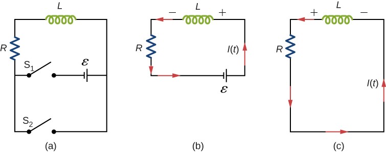
Apply Kirchhoff’s loop rule to get
$$ \varepsilon - L\frac{dI}{dt} - IR = 0 $$
wich gives the current through the inductor as a function of time
$$ I(t) = \frac{\varepsilon}{R} \left(1-e^{-Rt/L}\right) = \frac{\varepsilon}{R} \left(1-e^{-t/\tau_L}\right) $$
$$ V_L = -L\frac{dI}{dt} = -\varepsilon e^{-t/\tau_L}. $$
Thus the magnetic field energy stored in the inductor
$$ U_L = \frac{1}{2}LI^2 $$

Think about the significance of $\tau_L$ and the energy stored.
Now if there is no source emf in the RL circuit as shown in panel © of the first figure, the inductor will act as a source emf and according to the loop rule,
$$ IR + L\frac{dI}{dt} = 0. $$
Rearranging and evaluating the integral give
$$ I(t) = \frac{\varepsilon}{R} e^{-t/\tau_L} $$
$$ V_L(t) = -L\frac{dI}{dt} = \varepsilon e^{-t/\tau_L}. $$
5. Oscillations in LC circuits
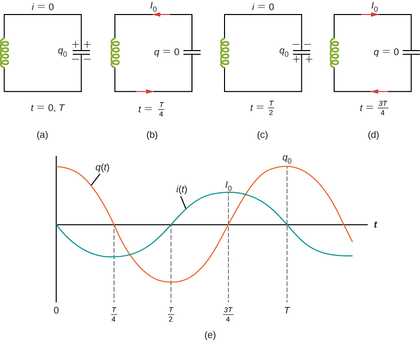
$$ U = \frac{1}{2}\frac{q^2}{C} + \frac{1}{2} Li^2 = \frac{1}{2}\frac{q_0^2}{C} = \frac{1}{2}LI_0^2. $$
Compare this with the conservation of energy in a mass-spring system:
$$ E = \frac{1}{2}mv^2+\frac{1}{2}kx^2. $$
If the equation of motion of mass is $x(t)=A\cos(\omega t+\phi)$ then for the charge we get
$$ q(t) = q_0\cos(\omega t+\phi) $$
and the angular frequency of the osillation
$$ \omega = \sqrt{\frac{1}{LC}}. $$
And the current as a function of time
$$ i(t) = \frac{dq(t)}{dt} = -\omega q_0 \sin(\omega t+\phi). $$
6. RLC series circuits
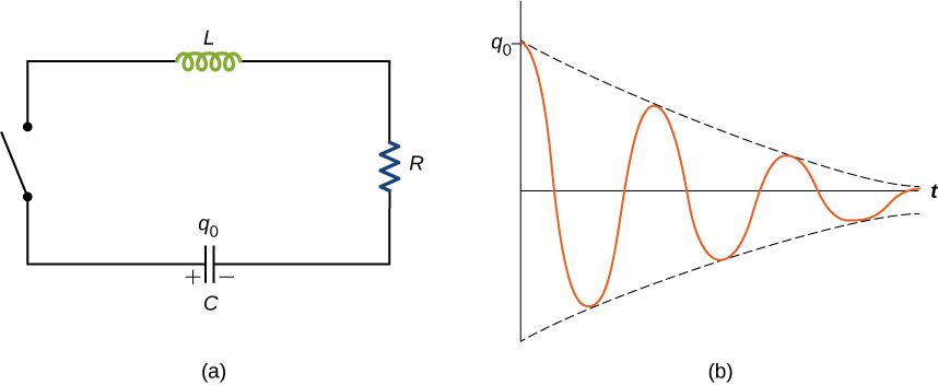
The electromagnetic energy is dissipated by the resistor as
$$ \frac{dU}{dt} = \frac{q}{C}\frac{dq}{dt} + Li\frac{di}{dt} = -i^2R $$
$$ \Rightarrow L\frac{d^2q}{dt^2} + R\frac{dq}{dt} + \frac{1}{C}q=0 $$
which is analogous to
$$ m\frac{d^2x}{dt^2} + b\frac{dx}{dt} + kx=0 $$
which has the solution
$$ x(t) = A_0 e^{-\frac{b}{2m}t} \cos(\omega t+\phi) $$
and we can write an analogous equation for the charge
$$ q(t) = q_0 e^{-Rt/(2L)} \cos(\omega' t+\phi). $$
where the angular frequency
$$ \omega' = \sqrt{\frac{1}{LC}-\left(\frac{R}{2L}\right)^2}. $$